Understanding Overcurrent Relays: Working Principle and Applications
 Selvakumar S
Learn the working principle of overcurrent relays and explore their key applications in power system protection and electrical safety.
Understanding Overcurrent Relays: Working Principle and Applications
Struggling to grasp how overcurrent relays actually work? You’re not alone. These protective devices are critical in isolating faults and preventing equipment damage in power systems. In this blog, we’ll walk you through the working principle of overcurrent relays and their real-world applications. Get ready to turn confusion into clarity—one concept at a time.
I. Introduction
In electrical power systems, protection is not optional—it's essential. At the heart of many protection schemes lies the overcurrent relay, a device designed to detect excessive currents and disconnect the affected portion of the network. Simply put, an overcurrent relay senses when current rises above a predetermined threshold, then issues a trip command to the circuit breaker. This prevents dangerous conditions like overheating, equipment damage, or even catastrophic failure.
Why does overcurrent protection matter?
Think of an electrical grid as a highway for electrons. Much like a traffic jam can cripple traffic flow, a fault current can overwhelm electrical equipment. Imagine a transformer overloaded or a motor burning out—these scenarios can lead to costly downtime, unsafe conditions, and major disruptions. Overcurrent relays are the first line of defense, identifying abnormal current flow and preventing wider damage. They don’t just protect machines—they safeguard entire systems and personnel.
In this blog, we’ll cover everything you need to know: the working principle of overcurrent relays, various types including the popular IDMT Relay, real-world applications in distribution systems, transformers, generators, and motors, as well as key advantages and limitations. By the end, you’ll understand why overcurrent relays remain foundational in protection schemes, and how to use them effectively in your work.
II. Working Principle of Overcurrent Relays
At its core, an overcurrent relay operates on a very simple concept: detect excessive current, then trip fast and isolate the fault. When current surpasses the relay's pickup setting, an internal mechanism triggers the circuit breaker. However, there’s more to it, and understanding the components involved helps grasp the full picture.
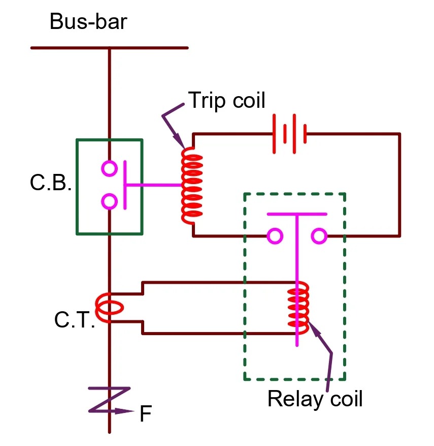
Key components include a current transformer (CT), the relay unit itself, and a trip mechanism. The CT is like a sensor—it measures the actual current in the line and converts it into a lower, controlled value. This measured current flows through the relay, which continuously monitors whether it crosses a preset limit. If it does, the relay sends a trip signal to the circuit breaker, which opens and disconnects the faulted segment.
Relays support different tripping mechanisms. Instantaneous tripping reacts immediately when the current threshold is exceeded, without any deliberate delay. This is critical for preventing high-energy faults from causing damage. In contrast, time-delayed tripping intentionally waits for a set duration before acting, which supports coordination with other protection devices downstream.
A more advanced method, widely used in distribution networks, is the Inverse Definite Minimum Time (IDMT) characteristic. With IDMT relays, tripping time decreases as fault current increases. In practical terms, a small overload causes a longer delay, but a heavy fault triggers a fast response. This blend of speed and selectivity makes IDMT relays well-suited for modern electrical systems.
III. Types of Overcurrent Relays
Overcurrent relays aren’t one-size-fits-all; engineers choose the right type based on system needs. The four main types are Instantaneous, Time-Overcurrent, Definite Time, and IDMT relays.
Instantaneous Overcurrent Relay (IOC) operates with no intentional time delay. The moment the current exceeds the pickup setting, the relay trips. This rapid response is useful near fault sources but can cause unnecessary outages if used without coordination.
Time-Overcurrent Relay (TOC) operates after a time delay that varies with fault current magnitude—higher currents produce faster response. This helps coordinate with downstream devices, reducing system-wide disruptions.
Definite Time Overcurrent Relay (DTOC) applies a fixed delay after the current crosses the threshold, regardless of fault level. This simplifies coordination in systems where a set delay suffices.
Inverse Time Overcurrent Relay (IDMT) enhances protection systems with dynamically varying response: faster trip times for heavier faults, slower for lighter over-current conditions. This adaptive behavior ensures both safety and coordination across protection zones.
IV. Key Applications of Overcurrent Relays
Overcurrent relays are highly versatile and applied across various contexts in power systems.
In distribution systems—both LV (low voltage) and MV (medium voltage)—they isolate faults in feeders and branches, protecting lines and avoiding system collapse. Selective coordination ensures only the faulted section is isolated.
Transformers are expensive and susceptible to damage during overloads or internal faults. Overcurrent relays placed on transformer feeders or windings offer crucial protection, preventing overheating or winding burnout.
Generators and motors—especially in industrial settings—benefit from overcurrent protection against locked rotor conditions or sustained overloads. By tripping before motors overheat or generators stall, these relays help maintain performance and extend equipment life.
Industrial power networks often deploy a zone-based protection scheme. Different network segments—such as main feeders, motor groups, and campus distribution—are shielded by carefully coordinated overcurrent relays, maintaining operational stability during faults.
V. Coordination and Settings
Proper configuration of overcurrent relays is essential. Selectivity and discrimination ensure only the faulted zone is disconnected. This requires setting pickup currents just above normal operating levels and adjusting time delays based on network hierarchy.
Overcurrent relays must also coordinate with other protection devices, such as distance relays, differential relays, and earth fault relays. Proper coordination avoids simultaneous operation of multiple relays, which can unnecessarily trip larger network sections.
Factors such as load profile, system voltage, and fault levels are crucial for tuning settings. A relay configured for low load may misidentify normal surges as faults, while one set too high may fail to detect actual faults. Engineers study load curves and fault studies to optimize relay coordination.
VI. Advantages and Limitations
Overcurrent relays bring several clear benefits. They are cost-effective, easy to configure, and widely used across utility and industrial settings. Simple to use, available in both electromechanical and digital forms, they remain a trusted tool for basic protection schemes.
However, they have limitations. They don’t inherently differentiate between nearby and distant faults—unless properly timed and coordinated. In complex grids with multiple interconnections or large-scale systems, their selective capabilities may fall short. In such environments, overcurrent relays are often supplemented with more advanced protection systems like distance and differential protection for full coverage.
VII. Conclusion
Overcurrent relays form a backbone component in electrical protection systems. From their basic working principle—monitoring current and triggering trip signals—to their various types (IOC, TOC, DTOC, and IDMT), they offer essential protection across multiple applications. Whether protecting distribution feeders, transformers, generators, or industrial networks, the correct implementation and coordination of overcurrent relays ensure effective fault isolation without disrupting service.
While they have limitations, especially in highly interconnected grids, careful design and use alongside advanced protection schemes enable them to serve as reliable workhorses in most electrical systems.
By understanding how overcurrent relays operate, where they fit in your protection scheme, and how to configure them correctly, electrical engineers can design safer, more resilient systems. This knowledge is also vital for technicians who implement and maintain protection settings on the field.
For additional resources, consider enrolling in a Protection Relay Configuration Workshop, attending hands-on IDMT Relay Coordination Webinars, or downloading our Protection Relay Settings Checklist. These tools can help you gain deeper proficiency with overcurrent protection—and ensure your systems are safe, secure, and reliable.
Categories: : Protection
Not sure how to get started with design engineering? want a free consulting call?
We’ve got you covered!
Fill out the form to get personalized guidance on how to:
✱ Transform your career in electrical engineering
✱ Discover the best tools and software to learn
✱ Identify the next steps to take toward design engineering
Start your journey today!