Step-by-Step Guide: How to Conduct an Arc Flash Analysis
 Selvakumar S
Learn how to conduct an arc flash analysis to ensure electrical safety, meet compliance standards, and protect workers from hazards.
Why Do We Need to Perform an Arc Flash Study?
Performing an arc flash study is essential to ensuring the safety of workers by identifying and quantifying potential hazard levels in an electrical system, which helps in determining the arc flash boundary and incident energy levels at various locations. This study is crucial for compliance with industry standards and regulations, such as IEEE Standard 1584, and provides detailed incident energy calculations necessary for determining appropriate personal protective equipment (PPE). Additionally, the results contribute to a comprehensive electrical safety program, allowing for the development of safety strategies, safe working distances, and lockout/tagout procedures. It also helps reveal weaknesses in system design and maintenance needs, enabling improvements that enhance safety and reliability. Finally, the findings from an arc flash study are valuable for training and raising awareness among workers about potential hazards and risk mitigation techniques.
What is the outcome of the arc flash study?
An arc-flash hazard analysis can be conducted alongside or as an extension of a short-circuit study and a protective-device coordination study. While a complete coordination study might not be necessary, it is essential to apply the protective device opening times in response to arcing currents during the analysis process. The key deliverables of the arc-flash hazard analysis are the arc-flash boundary and the arc-flash incident energy at specified working distances from the arcing source at designated locations within the electrical system. The study results document the incident energy analysis, providing crucial information for workers to use as part of a comprehensive electrical safety risk assessment.
What are the steps involved in an arc flash study?
Step 1: Collect the system and installation data
Step 2: Determine the system modes of operation
Step 3: Determine the bolted fault currents
Step 4: Determine typical gap and enclosure size based upon system voltages and classes of equipment
Step 5: Determine the equipment electrode configuration
Step 6: Determine the working distances
Step 7: Calculation of arcing current
Step 8: Determine the arc duration
Step 9: Calculate the incident energy
Step 10: Determine the arc-flash boundary for all equipment
Step 1: Collect the system and installation data
Begin by gathering comprehensive electrical system data, including up-to-date single-line diagrams, time-current curves, and short-circuit models. This involves field verification to ensure documentation integrity. Collect data on all low-voltage distribution and control equipment within the scope of the study, including equipment like switchgear, motor control centers (MCCs), switchboards, and more. Record detailed information on transformers, generators, large motors, and switchgear, including voltage levels, ampacity, and impedance data. Additionally, gather data on conductors, cables, instrument transformers, and protective devices, ensuring all information is current and accurate.
Step 2: Determine the system modes of operation
Identify all possible operating modes of the electrical installation. This includes various configurations, such as multiple utility feeders in service, different substation setups, and generators operating in parallel with the utility supply. It is crucial to consider both the maximum and minimum available short-circuit currents for each mode of operation. Evaluate the actual operating modes based on site conditions, including maintenance and special operating conditions.
Step 3: Determine the bolted fault currents
Perform a short-circuit study to establish the bolted fault currents at different points in the system. This study should consider both the system data and the various modes of operation identified in Step 2. If an existing short-circuit study is not available, a new one must be conducted to ensure accurate fault current calculations.
Step 4: Determine typical gap and enclosure size based upon system voltages and classes of equipment
Analyze the typical gap between conductors and the enclosure size for the specific voltage levels and classes of equipment. This includes understanding the dimensions of the enclosures and the spacing of the electrodes, which are critical for accurate arc-flash calculations. Equipment enclosure sizes should follow the guidelines provided in the standard to maintain consistency in calculations
Step 5: Determine the equipment electrode configuration
Identify the electrode configurations for the equipment being studied. This includes configurations such as vertical conductors inside a box (VCB), vertical conductors terminated in an insulating barrier (VCBB), and horizontal conductors in a box (HCB). Accurate identification of electrode configurations is essential for calculating the arcing current and incident energy.
Step 6: Determine the working distances
Establish the working distances for personnel from the potential arc source. These distances are crucial for calculating the incident energy that a worker might be exposed to during an arc-flash event. Typical working distances are defined by the type of equipment and the voltage levels involved
Step 7: Calculation of the Arcing Current
Calculate the arcing current using the system parameters and electrode configurations determined in the previous steps. This involves applying the IEEE 1584 model, which provides formulas and methods for estimating the arcing current based on the collected data and equipment characteristics
Step 8: Determine the arc duration
Identify the arc duration by evaluating the protective device's response time to arcing currents. This includes analyzing the time-current characteristics of circuit breakers, fuses, and protective relays. The arc duration significantly affects the incident energy calculation, as longer durations result in higher energy exposure
Step 9: Calculate the incident energy
Calculate the incident energy at defined working distances from the arc source. This calculation uses the arcing current and arc duration data to estimate the energy level a worker might be exposed to during an arc-flash event. The results are critical for determining appropriate personal protective equipment (PPE) and safety procedures
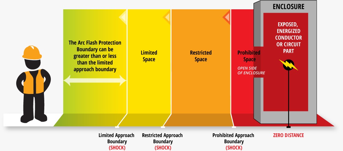
Step 10: Determine the arc-flash boundary for all equipment
Establish the arc-flash boundary for each piece of equipment. The arc-flash boundary is the distance at which the incident energy drops to a level that poses a minimal risk of injury to personnel. This boundary helps define safe working zones and the necessary precautions to protect workers from arc-flash hazards
Cautions and Disclaimers
- Ensure all collected data is accurate and up-to-date. Inaccurate data can lead to incorrect calculations and increased risk.
- Only qualified individuals with appropriate knowledge and experience should perform arc-flash hazard analyses.
- Regular maintenance and testing of protective devices are crucial to ensure they function correctly during an arc-flash event.
- Adhere to relevant industry standards and guidelines throughout the analysis process.
- Use the results of the arc-flash hazard analysis as part of a comprehensive electrical safety risk assessment to implement effective safety measures and procedures
Categories: : Arc Flash
Not sure how to get started with design engineering? want a free consulting call?
We’ve got you covered!
Fill out the form to get personalized guidance on how to:
✱ Transform your career in electrical engineering
✱ Discover the best tools and software to learn
✱ Identify the next steps to take toward design engineering
Start your journey today!